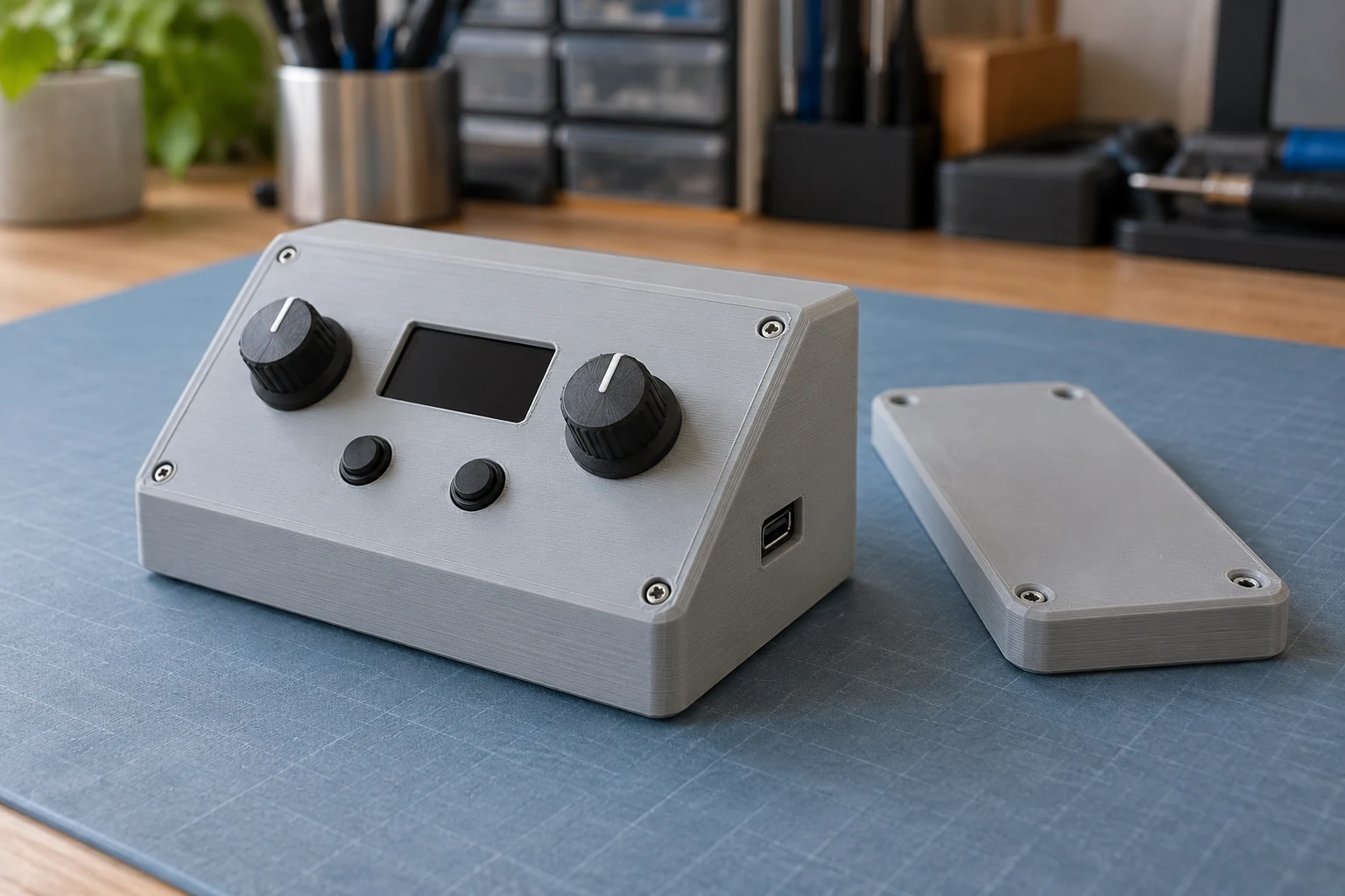
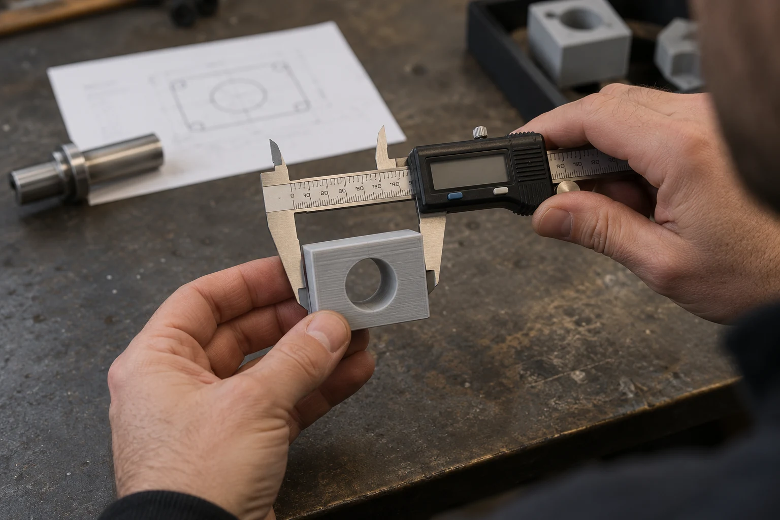
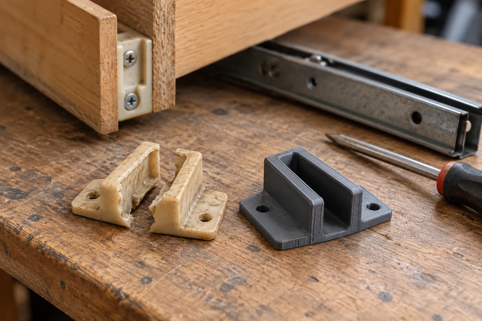
A printed assembly can use screws and nuts, designed-in inserts or snap fits. The choice depends on load and how often it will be taken apart. Hardware, additional operations and connection testing are agreed separately from ordinary printing.
Work through the assembly sequence first
Will the cover open once or every day? Can you reach a nut from behind? Will a screwdriver fit after the object is mounted on a wall? These questions influence the connection design. A neat enclosure can be impractical if its last screw cannot be tightened around the installed cables.
Sketch the assembly sequence and mark fixed components. For a new connection, a small representative section can be tested before printing the entire housing. It needs the actual dimensions and material; an arbitrary enlarged copy does not establish how the final feature will behave.
Allow room for the actual fastener
If rear access is available, the design can provide for a nut. Leave room to insert and retain it. Give the fastener type and dimensions before modeling. “A small screw” does not explain the head, length and thread that need to fit.
For a screw fixed directly into plastic, hole geometry, material and tightening conditions matter. A printed hole should not automatically be treated as a durable thread, particularly when a lid will be removed regularly. Check the connection separately from the apparent strength of the enclosure wall.
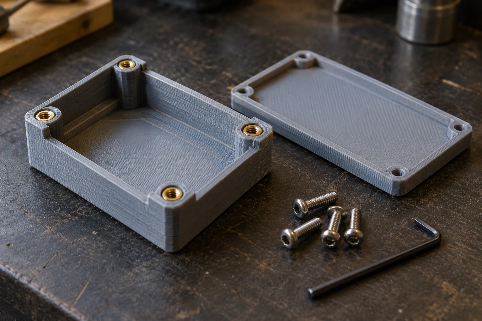
Discuss inserts for repeated disassembly
A threaded insert provides a metal thread within a plastic part. Its seat is designed around the particular insert’s dimensions. The surrounding wall and load direction still contribute to the connection’s strength. Enlarging a hole by eye in an existing model is not a reliable specification.
State the thread size and expected frequency of disassembly. Hardware supply and insert installation are not automatically included in the calculator price. Agree feasibility, contents and cost before ordering. If you will install the inserts, confirm the exact seats needed in advance.
Test a snap fit in its real geometry
A snap fit needs the right travel, access for release and room to open. Explain whether the cover should be removed by hand or the joint is intended to stay closed. A thicker rigid bridge is not automatically better; its shape needs to provide the required movement without excessive force.
For a new design, test a sample in the agreed material. Check closure, release and retained shape after several cycles. A specified service life needs testing for that requirement. General material properties do not replace a trial of the actual snap feature.
Include the connection in the brief
Send an assembly sketch, fastener dimensions, load direction and expected opening frequency. Identify contact faces and permitted clearance. The accuracy guide explains why layer height alone is not a promised fitting tolerance.
Estimate a ready STL or OBJ in the calculator. If the connection still needs designing, use the modeling form. For an electronics enclosure, show the board and cables from the start so the closing method suits the complete assembly.
Common questions
Does the printing price include screws and inserts?
Not automatically. Hardware, its supply and installation are additional order requirements that must be agreed separately.
Can a lid be made without screws?
Snap fits or another connection can be discussed. Explain the opening frequency and available space, then test a new design on a sample.
Technical references
Manufacturer guides explain printing and design principles. We agree the requirements for your particular part before production.
Find out what your model will cost.
Upload an STL or OBJ. If you do not have a file, send photos, a sketch and measurements. Modeling and printing are quoted separately.
Back to DECORDS 3D